FRS
Friction Reduction System
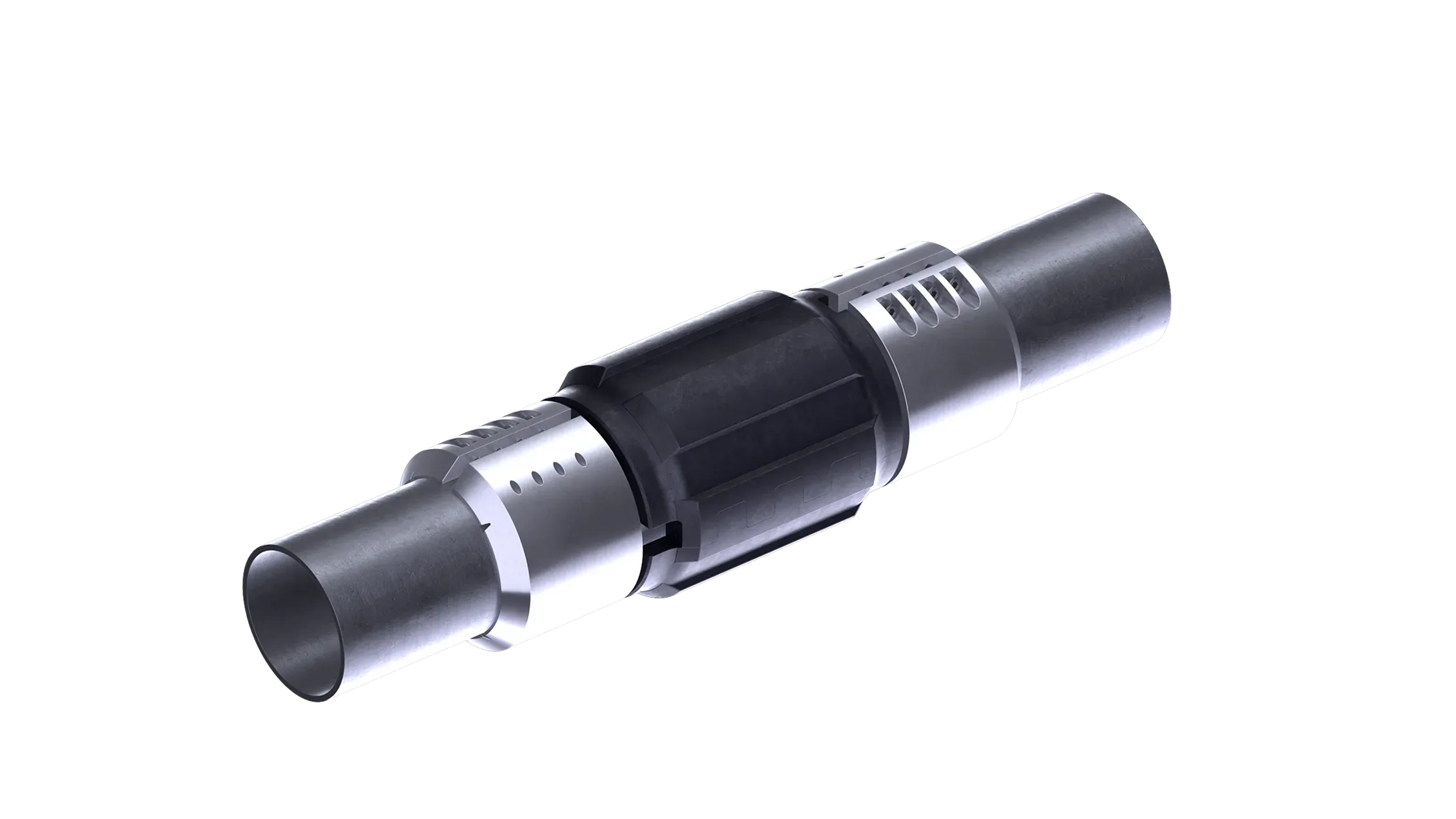
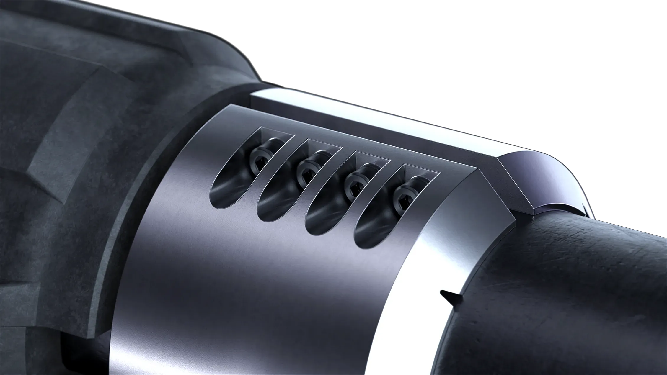
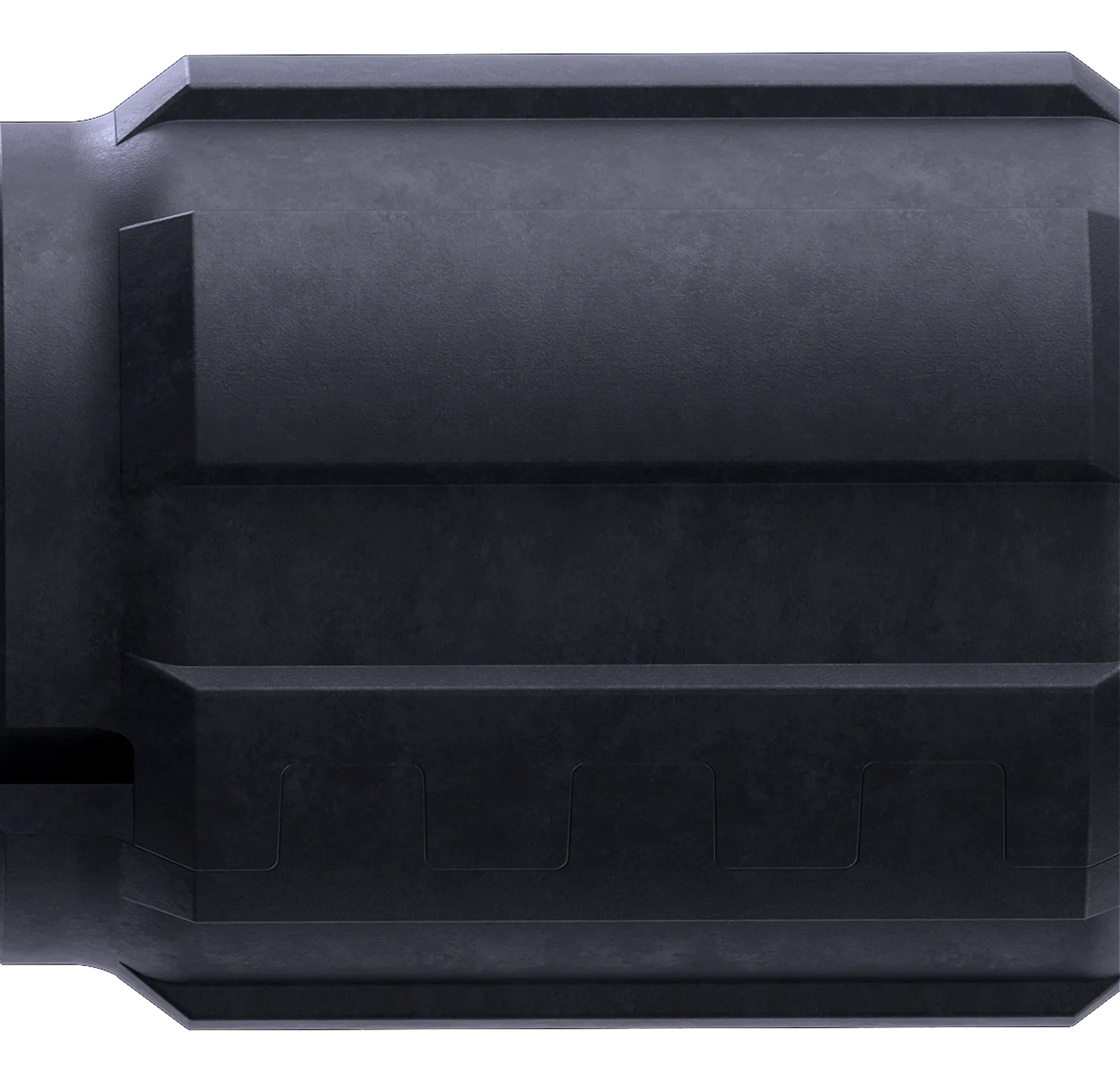
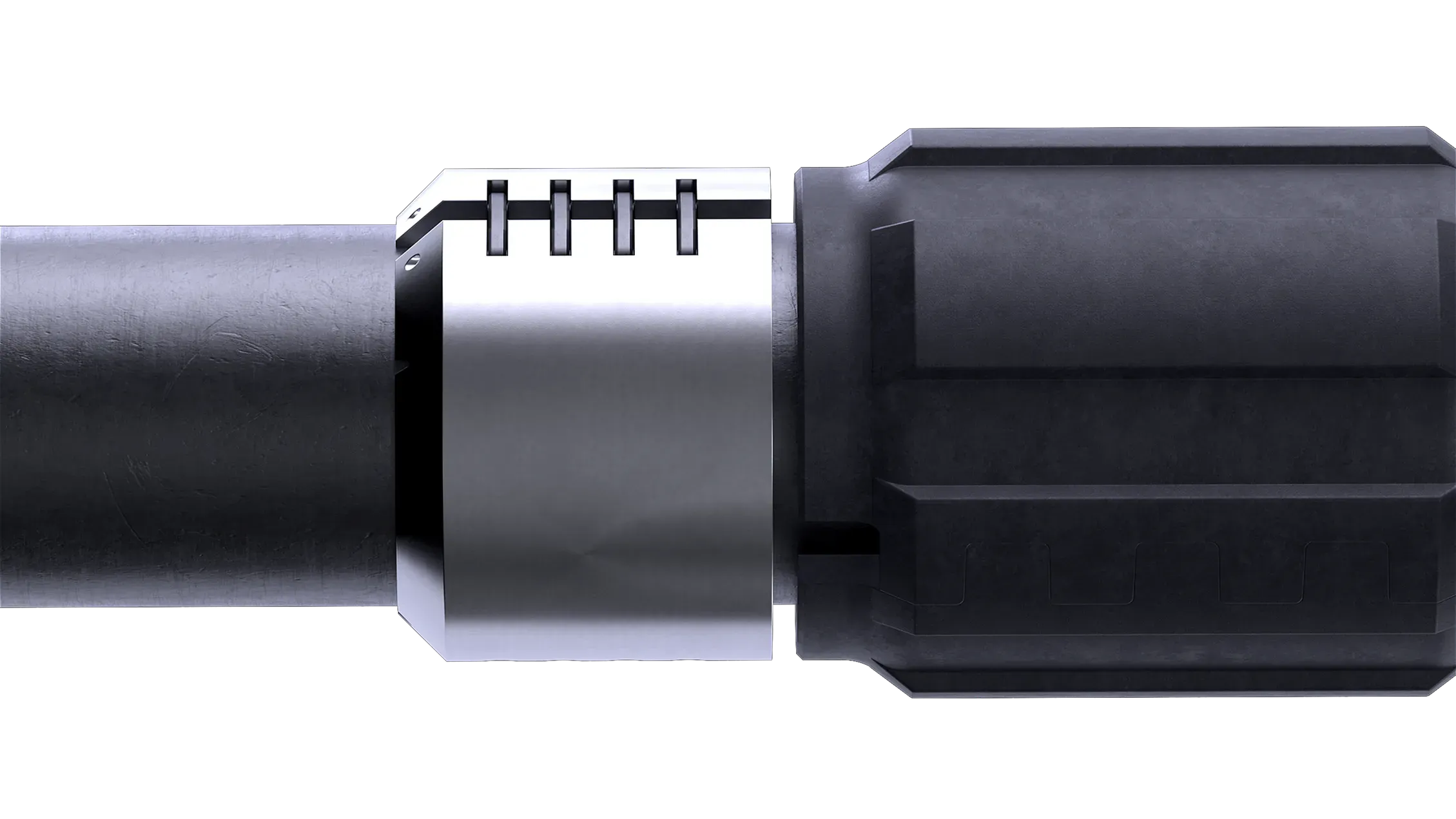
Frameless composite friction reducers. Installed on the drill pipe in zones of maximum side load. The pipe rotates inside a stationary composite sleeve pressed against the wellbore wall.
Test results
Bench testing at SPBPU (Peter the Great) and field testing across 9 pilot runs confirmed both axial and circumferential friction reduction relative to steel.

Plain-bearing principle
The drill pipe rotates inside a stationary composite sleeve. The sleeve is pressed against the wellbore wall or casing by lateral load — never touching the pipe body.
Friction coefficient < 0.06
Low-friction composite — our in-house Kompozit №1. For reference: steel on steel runs at 0.13 in the lab. 2×+ less friction.
1–2 min to install
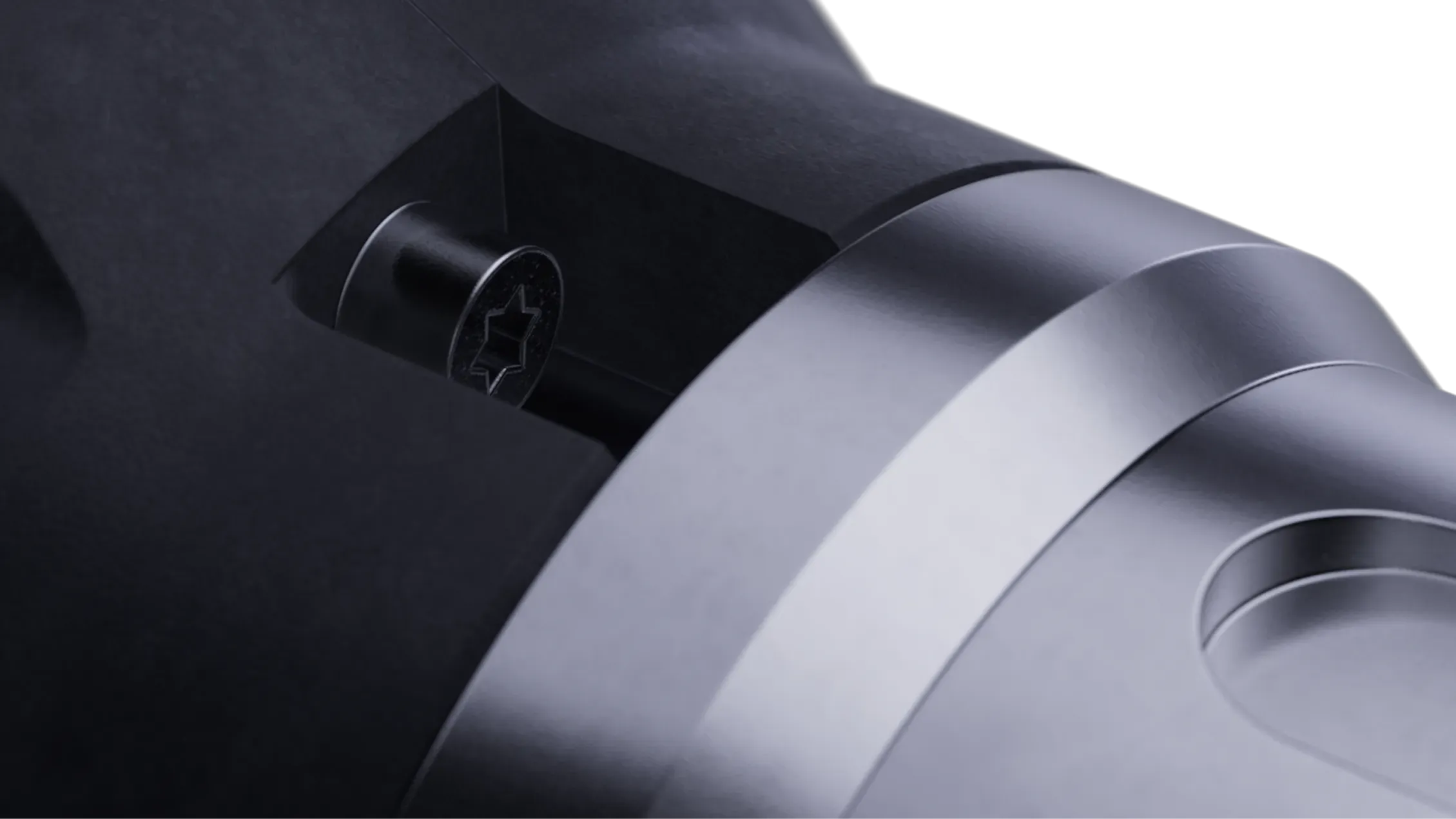
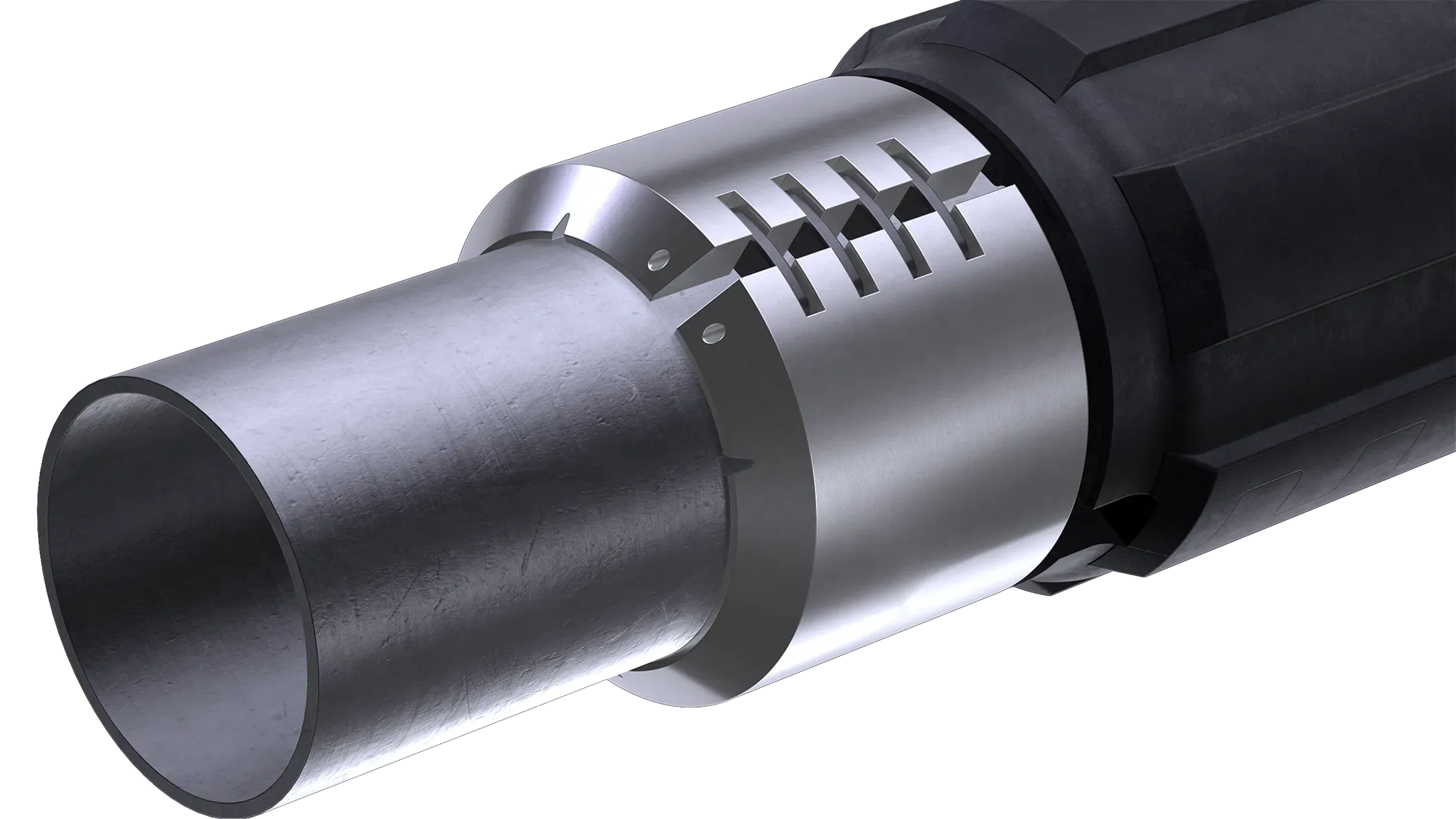
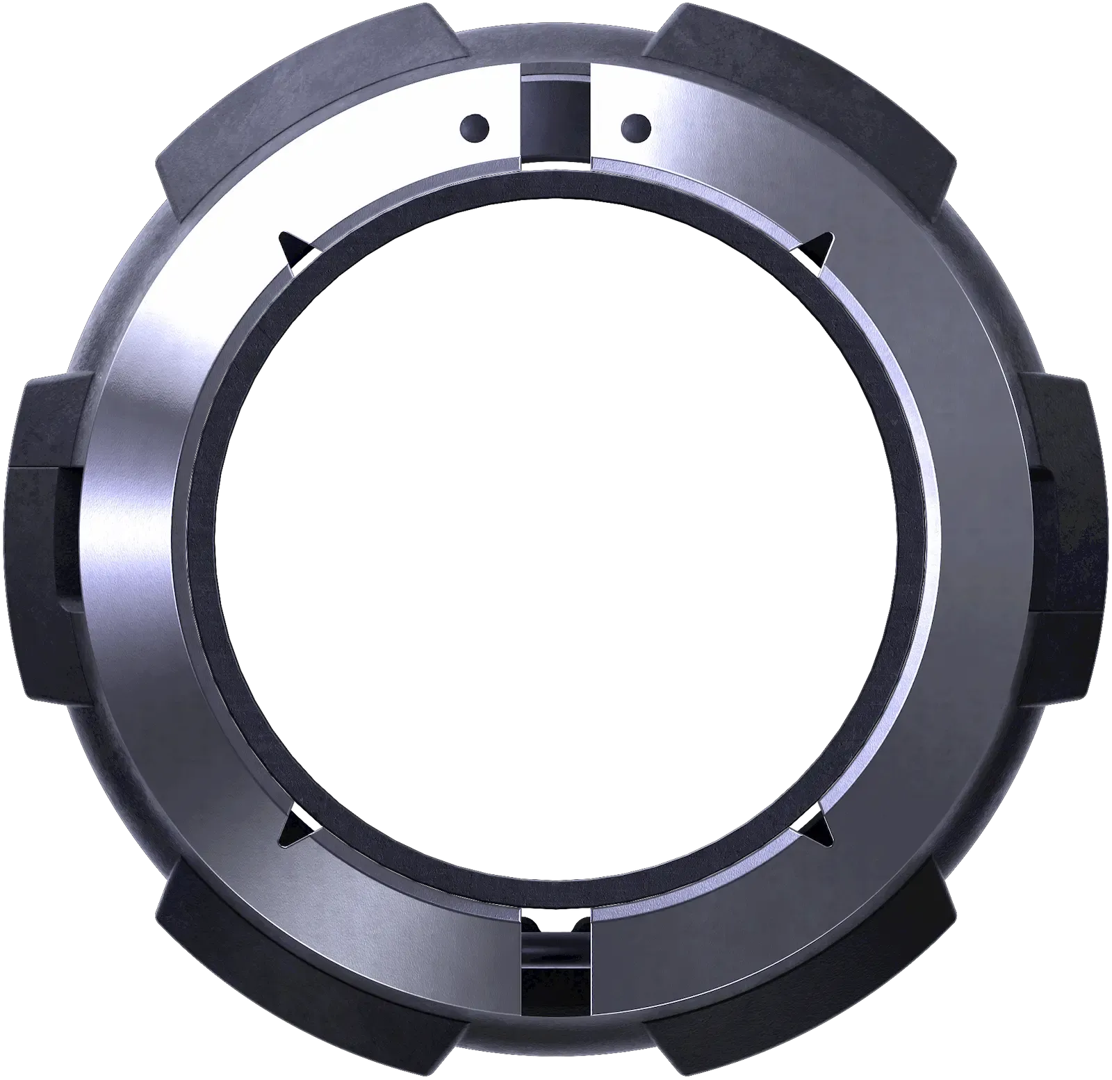
Mounts on the pipe during a trip or on the catwalk. Held by two high-strength aluminum stop collars (4×M8, class 10.9). No steel frame, no hinges inside the sleeve.
2M-revolution service life
2M revolutions in cased hole, 500k revolutions in open hole. Wear rate 0.01 g/cm² per GOST 13087-2018.
Kompozit №1
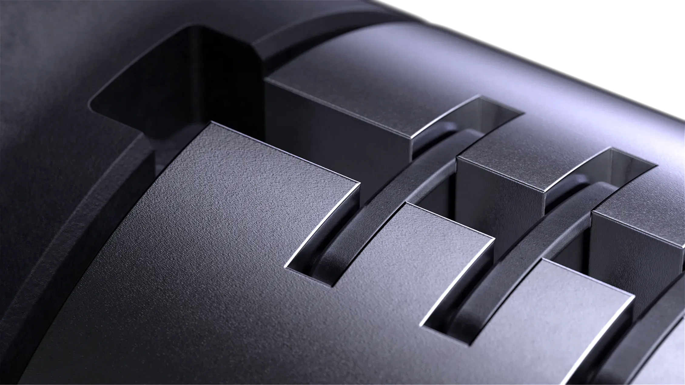
SSTR's own formulation. Low-friction composite. Frameless — no steel reinforcement inside the sleeve.
| Parameter | Value |
|---|---|
| Friction coefficient μ | 0.06 (wet, on steel; steel-on-steel: 0.13) |
| Axial friction reduction | −64% vs steel |
| Circumferential friction reduction | −51% vs steel |
| Max rotational speed | 200 rpm |
| Steel frame | None |
Sizes
| Parameter | FRS-89 | FRS-102 | FRS-127 | FRS-149* |
|---|---|---|---|---|
| Pipe size, mm | 89 | 101.6 | 127.0 | 149.2 |
| System length, mm | 510 | 510 | 510 | 510 |
| Max lateral load, kgf | — | 2200 | 2500 | 2200 |
| Stop collar — axial force, tf | — | 7.5 | 8.0 | 10.0 |
| Service life (cased), k revolutions | — | 2000 | 2000 | 2000 |
| Service life (open hole), k revolutions | — | 500 | 500 | 500 |
*FRS-149 — pilot batch. Max temperature 100°C, stop collar make-up torque 25 N·m. FRS-89 specs being finalized — datasheet in progress.
What FRS is used for
- 01
Torque reduction at the rotary table / top drive
- 02
More weight on bit transferred downhole
- 03
Lower hook load when pulling out of hole
- 04
Less drilling vibration in the installation zone
- 05
Drill pipe and casing wear protection

Run the numbers on your well
Send your well data and constraints — we'll run T&D modeling and come back with a configuration and the expected impact.